1. Driving Coil
Can be AC OR DC Driven Coil Relay
Can be AC OR DC Driven Coil Relay
a) Minimum Coil Voltage
The reference for Minimum Coil Voltage for proper operate of a Relay Can be taken from those mentioned in the Detailed Catalogues
b) Maximum Coil voltage
The Maximum coil Voltage to the Relay Coil can be calculated in such a way that the sum of the maximum ambient temperature in addition to the relay coil temperature and warming due to current load in contacts should not exceed the maximum allowed value.
Defined as the Voltage Applied to the coil at which the Relay Contacts Switch Position from NC to NO Contacts.
Defined as the Coil Voltage at which the Relay Contacts Switch Position from NO to NC Contacts. Strong external magnetic fields (e.g. from other neighbouring polarized relays or permanent magnets) may influence the operate and release values.
Contact Configurations and their Definitions as follows
1. 1 FORM A / SPST (NO) / 1 / 1NO : One Make Contact, Single Pole Normally Open Relay
2. 1 FORM B / SPST (NC) / 2 / 1NC : One Break Contact, Single Pole Normally Closed Relay
3. 1 FORM C / SPDT / 21 / 1CO : One Break and One Make Contact, Single Pole Change Over Relay
4. 2 FORM A / DPST (NO) / 2NO: Double Make Contacts, Double Pole Normally Open Relay
5. 2 FORM B / DPST (NC) / 2NC: Double Break Contacts, Double Pole Normally Closed Relay
6. 2 FORM C / DPDT (CO) / 2CO: Double Make and Double Break Contacts, Double Pole Changeover Relay
7. 3 FORM A / 3PST (NO) / 3NO: 3 Make Contacts, 3 Pole Normally Open Relay
8. 3 FORM B / 3PST (NC) / 3NC: 3 Break Contacts, 3 Pole Normally Closed Relay
9. 3 FORM C / 3PDT / 3CO: 3Break Contacts and 3 Make Contacts, 3 Pole Changeover Relay
i.e. Double Pole Relays and 3Pole Relays from our range please note the following –
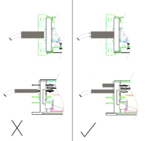
If neighbouring contact sets within the same relay switch essentially different voltages and arcs at the contacts occur, a short circuit between the sets by the arc can occur. Our Relays have a very special and unique feature where in Internally there is complete Isolation between the multiple poles and therefore complete protection form arc jump. However the short circuit can still occur at the Customer end of the relay between the Power Terminals. To prevent this and ensure a nil field rejection it is extremely important that Proper Tight Fitting Sleeving be used on the terminals after fitting Snap on Lugs Or Soldering the wires.
The Sleeving should Always Overlap the Anti tracking partition on the Relay provided between the multiple contact sets. Even if it is a DPST relay or 3PST relay, the dummy terminals are also required to be insulated by proper sleeves.

a) Continuous Contact Current
The Maximum Current (RMS-value at AC) that Previously Closed Relay Contacts Can Continuously carry.
b) Inrush Current / LRA (Locked Rotor Current)
The Maximum Inrush Current that can momentarily flow through the Contacts of the Relay. This is typical in Switching Inductive and Capacitive Loads. Please refer the specs in detailed catalogues of our Relays
In case of Switching High Power Loads in a Changeover Relay from NO to NC, an Arc forms, originating first at the breaking contact. If the Contact gap is insufficient the Arc continues to the making contact, thus Causing a short circuit. In such High Power Switching applications, a Relay with a sufficiently large contact gap should be used. Typical applications with such conditions are Automatic Genset Changeovers or Genset Changeover Switches (ATS).
Please feel free to consult the Factory for any other Technical Details that may be required for Optimum Selection and use of the Relays.
Before approving any component for mass-production, we strongly recommend to test these products under a situation close to the final production situation, to ensure a trouble-free production process and subsequent product function. The decision on the suitability of the product is the solely liability of the customer.
The operation beyond the specification of our products carries the risk of dangerous conditions.
All our product data are shown in the specifications are subject to change, and are designated for users with expertise and experience in implementation of these technical data
© 2021 Tara Relays Pvt. Ltd. All Rights Reserved. Developed by Quantazone.